Tag Archive for: arduino

Chain Reactions (with electronics)

Like everyone else delivering ‘maker’ education, we use chain reaction machines in some of our workshops. There’s a lot of fun to be had, and some intriguing mechanisms to be discovered. But there are also some classic problems:

  1. Connecting bits of a chain reaction machine together is fraught with difficulty. It’s typically the links that fail, and that can lead to frustration when it’s not clear who ‘owns’ the connection.
  2. There’s a tendency for everything to start high and finish low, and hence for each stage to run out of energy somewhat.

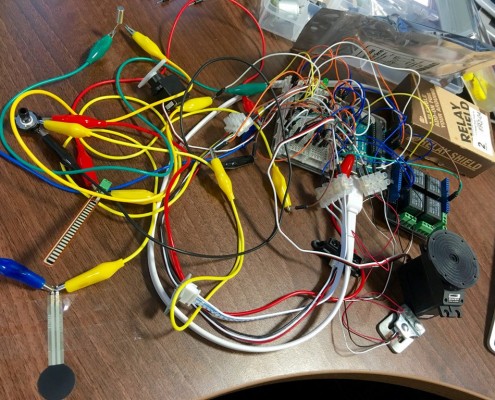
One of the things we’ve been playing with attempts to solve both problems, by chucking a bit of electronics into the mix. We use Arduinos as control circuits, running some code which is fairly readily tweaked to handle one of a range of inputs, including:

  • Straightforward ‘short to ground’ switches
  • Light-dependent resistors
  • Force- and flex-sensitive resistors
  • IR distance sensors
  • Tilt switches
  • Hall Effect magnetic field switches

The software is configurable into a couple of different modes, but is typically set to trigger on a threshold reading and operate either a servo, or a continuous-rotation servo as a low-speed motor.

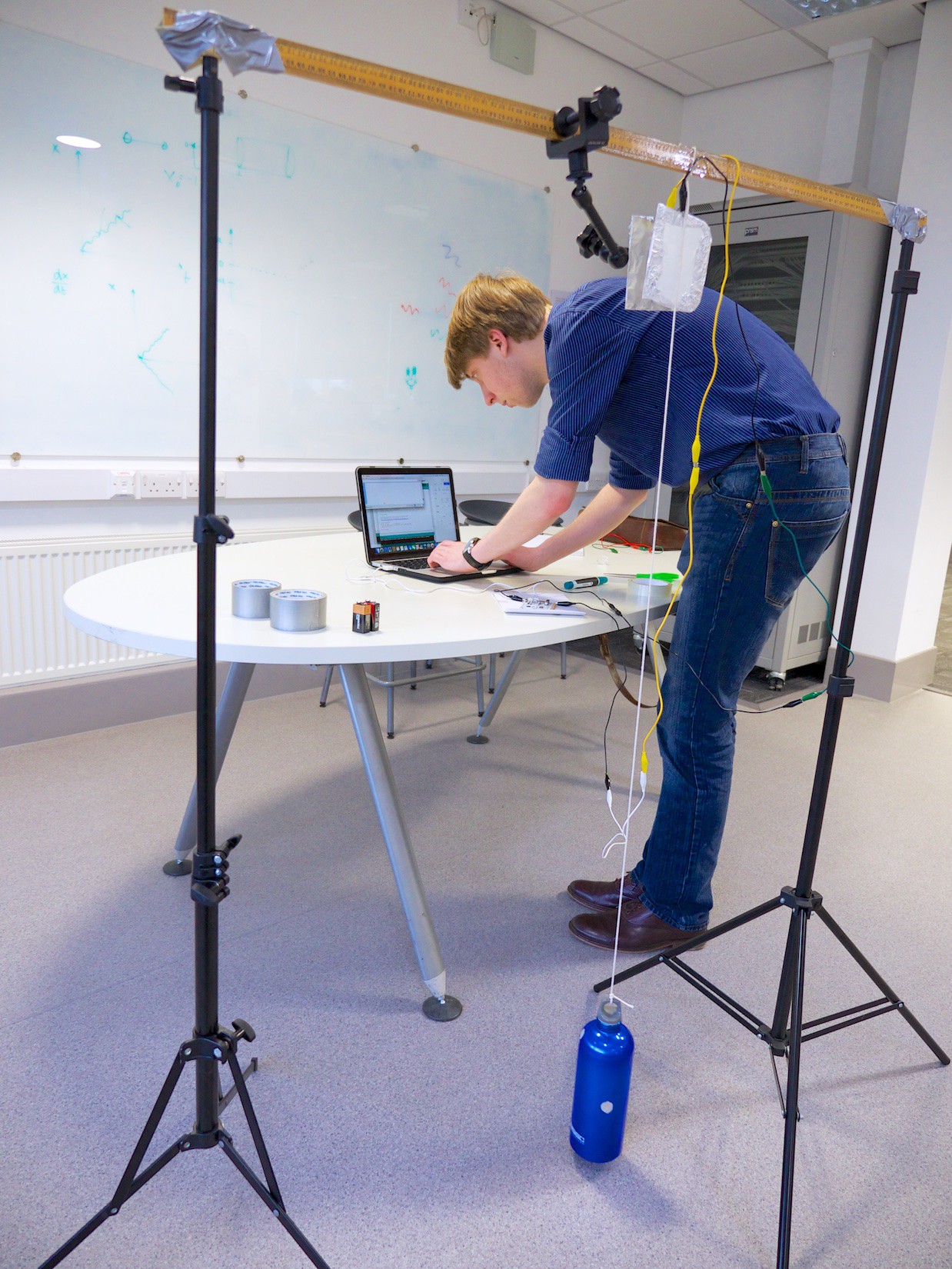
The resulting chain reaction machines integrate physical and electronic segments, and splicing them together is hence usually a case of running longer wires from a sensor at the end of one segment into the Arduino which controls the trigger for the next. Last week we ran an end-of-term workshop with 15 year-olds from one of our partner schools, who came up with the machines you see in these two films. We think they did a cracking job.

Now, we don’t use this workshop very often. The challenge, we find, is that there are so many alien pieces of technology that participants tend to freeze rather than try things out and explore. These groups worked particularly well, but more generally we (unexpectedly?) find this to be a better workshop with primary groups than secondary. Younger children tend to be more receptive to (or familiar with?) failure and iterative development.

However, when the workshop comes together it can produce some outstanding results. We think there’s some mileage in the approach, and we’ll continue to refine the idea.

The code we’re using is on Github, I’m afraid with rather minimal documentation at present. I’ll try to include part details for the sensors, but the code comments should walk you through most of it.

RI Engineering Masterclass: Chain Reaction

My desk, earlier in this week.

My desk, earlier this week.

If you have the misfortune of following my Twitter feed, you may have noticed a flurry of posts this past week with pictures like the insanity in the heading, or this tumble of wires.

All is now revealed: I was prepping for a new workshop, delivered for the first time this morning to the poor unsuspecting members of our Autumn 2015 cohort for the Royal Institution Engineering Masterclass scheme. This was their sixth and last session, and we wanted to leave them with something creative, challenging, and just a little ridiculous.

There are lots of ‘chain reaction’ type workshops around, and while they’re a heap of fun they tend to go big on the trial-and-error aspect of engineering. I wanted something just a little more thoughtful that brought in a wider range of elements. So the plan was hatched for each stage of the machine to weave in and out between the physical domain and the electronic.

That is: the connections between stages of the chain reaction wouldn’t all be mechanical. So we had a wide range of sensors, some Arduino code to handle those inputs, and a few different types of servos, relays and motors to transfer the electronic processing back into the mechanical realm.

It was a lot of try to pack into a 2½ hour workshop, but it almost worked. It helps that this bunch of Masterclass students are smart, capable and inventive, and they worked really hard to make something out of the session. We didn’t get a sustained chain of machines going, but here’s what they did, and what it all looked like:

Well done, everyone. I thoroughly enjoyed working with you, and you should be properly proud of your inventiveness and ingenuity.

Some of you were asking about the Arduino kits we use: I recommend Oomlout’s ARDX kits. There are other starter kits out there, often with glossier booklets to accompany them, but I’ve found Oomlout’s documentation to be better-written than most, and the range of components is good. They’re also one of the cheaper starter kits. You can buy directly from Oomlout (which is a lovely chap called Aaron who’s usually around at Maker Faire UK) or via Amazon. Other useful suppliers include Pimoroni and Kitronik.

The Arduino ecosystem is vast but fairly accessible, and the suppliers above have a huge range of breakout boards, add-on ‘shields’, sensor inputs, servos, and so on. The hardest part is starting to think of projects to apply all your new tools to – which is precisely why I like things like chain reaction machines or playing musical instruments. There are lots of books of projects like plant waterers or burglar alarms, but straight-up playing with this stuff gives you an excellent idea of the range of problems to which you might apply it all. In the end, I think guilt-free playing is the most effective route to learning about electronics and micro controllers, at least for these initial steps. Later on… well hey, people do degrees and apprenticeships and make careers in this stuff. But start with something you find amusing.

I’ll be making quite a few changes to the Chain Reaction workshop before I run it again. But I will run it again. Thanks again all!

Update Monday 23rd – the lovely folks at Cambridge Science Centre have this morning tweeted a link to this video. Wow.

Ohbot on Kickstarter

I may be a little obsessed with DIY robots. We’re gradually building up a robot menagerie in the Think Physics office, and I’m planning a comparative review of some of the available kits and plans. But that’s not ready yet, and in the meantime you may like to know about this:

I met Matt and Dan at BETT at the beginning of the year, where they had a tiny stand showcasing early prototypes of their Ohbot robotic head. Think Physics bought a couple – we were showcasing one of them at the Juice Festival last week, and you’ll see them around at more of our events over the coming months. I continue to be impressed by them, and the software’s particularly good. It’s Windows-only, but adopts a Scratch-like block programming system which is both straightforward and quite flexible.

Right now, the guys are back on Kickstarter with a more developed, easier-to-build and more expressive version of Ohbot. It’s turning even more into a robot puppet, and once they get over the injection moulding hurdle it should be considerably cheaper than the previous short-run laser cut prototypes.

Ohbot’s interesting because while it is a robotics and programming project, it’s also about self-expression, dialogue, emotion, and our responses to technology. I very much like the pure robotics approach of miniature robotic arm MeArm, and the accessible turtle-graphics programming focus of Mirobot, but Ohbot is a fascinating addition to the mix. For Think Physics’ purposes, I like it because it’s clearly using the same palette of components and techniques as our other robots, and it’s also doing something rather different. If the Maker movement is about any one thing, that thing has to be “technology put to creative use”, and Ohbot is an excellent invitation to think beyond Arduino coding and wiring components together, and to really explore how we want our technology to work for us.

The Ohbot2 Kickstarter closes on Sunday morning (!), and as I write this is tantalisingly close to success. If you can help it reach its target, do pledge for one of the rewards.

Update: Success!
The Ohbot2 Kickstarter was successful on Sunday, so the team are gearing up for full-pelt production in time for Christmas. Congratulations, guys!

Register your school for BBC micro:bit

Confused by Raspberry Pi and Arduino (not to mention Espruino, Beagleboard, Edison, and all the rest)? Don’t despair, things are about to get even more convoluted!

The BBC are introducing a whole new platform to the education mix, with their micro:bit available to every year 7 child in the UK. The board itself is the centrepiece of a whole education initiative, “Make It Digital”, which aims to build on the legacy of the original 1980s BBC Computer Literacy Project, which itself spawned the original BBC Micro. So, surrounding the new board will be a whole ecosystem of learning materials and projects. There’s also a rather interesting web-based programming tool, built on Microsoft’s TouchDevelop, which looks like it might neatly bridge the gap between popular introductory tools like Scratch and follow-on approaches like Python and Arduino’s C environment.

Arguments about whether the BBC should have gone this route are largely moot at this point – as a publicly-funded body it’s hard for them to be seen to back any commercial product, even if it’s wholly open (Arduino) or sort-of commercial but warm and cuddly (Raspberry Pi). Besides, the array of Make It Digital project partners is huge.

So micro:bit is coming, and hopefully bringing with it a vast array of high-quality resource material. And best of all, it’s all free. Or at least, one micro:bit per year 7 student will be – the rest of us will have to buy the things, but that’s still a great start.

Register your school now to receive micro:bits for your 2015 year 7 group, via this web form.

No, really: if you’re responsible for ICT in your school, fill the form in. Micro:bit might turn out to be a distraction, but there’s a decent chance it’ll be a superb platform and ecosystem for investigations and embedded projects. I’ll be trying to get my hands on a few micro:bits when they become more widely available, and I look forward to building things with them via Think Club.

Additional links:

Stepping into the (not-so-lime) light!

The Centre for Life’s forthcoming live science show In a Spin is being produced in collaboration with Think Physics. Today, therefore, has involved much sketching, planning and calculating, as Joe and Duncan from Life build props and set-pieces for the show.

Don’t be fooled by the cobbled-together appearance of the strip of lightbulbs above. Oh, no. That is a very rough-around-the-edges prototype. What it shows, however, is that we’ve done our sums more-or-less correctly, and we can indeed switch a bunch of lamps with a controller and a relay without blowing anything up unintentionally. Which would have been embarrassing.

Tomorrow, Joe’s world will revolve around a pile of laser-cut arrows, and new intern Callum will hopefully show us how to draw up a PCB which we can get fabricated by Northumbria’s magnificent milling machine.

I’d say ‘watch this space,’ but really, don’t: watch the show at the Centre for Life, from 16th June.

Tinkering Thursday: March 5th “Turn it off!” edition

Andrew has invented the ANNOY-O-TRON!! It’s in block capitals and has two exclamation marks, to be particularly annoying. A development of the previous instrumented pendulum, the ANNOY-O-TRON!! features several key advances:

  • Annoyingly many ‘compile / wait / upload / wait / fail / turn off / wait / turn back on / wait’ cycles.
  • Annoying choice of annoyingly loud GarageBand synthesised instrument.
  • Annoyingly flaky MIDI interface from the TouchBoard to GarageBand…
  • …which turned out to be caused by an annoyingly obvious-in-hindsight bug. Who knew that unless you turn a note off before playing a new one, GarageBand spawns a new instrument for each, topping out at 64 instruments? Harrumph. Annoying.
  • Annoyingly not-very-tremendous result in the end.
Andrew does battle with the less annoying parts of his code.

Andrew does battle with the less annoying parts of his code.

Annoyances aside: Andrew’s now turned the instrumented pendulum into something wholly more whimsical and ridiculous than, er, the sampled sine wave of previous weeks. He’s also had two sensors being synthesised at once, which obviously doubles the annoyance factor.

Next up: further exploring the MIDI controller aspect of this, to see how much flexibility there is to manipulate instruments rather than simply trigger notes. Then there’s building a frame, rigging a dozen pendulums, working out what and how we want to turn into what sort of sound, and thinking about what else we can drive with the data. Sound is only part of the excessive annoying extravaganza that will be this installation.

Tune in next Tinkering Thursday for tales of triumph over annoying adversity!

Andrew would like to make it clear that the annoyingly frequent use of the word ‘annoying’ in this update is not his responsibility.

Tinkering Thursday: 19th Feb “In the swing of it” pendulum edition

Our charmingly softly-spoken volunteer Andrew is filling in some time before his own physics degree by… actually, I’m not entirely sure why he’s here, but he didn’t seem to mind when I dropped a Bare Conductive Touchboard set in front of him and said ‘Here, get that working.’ We always have things going on we can rope people into.

Touchboard is a nifty little circuit board which integrates an Arduino controller, an audio engine, and a multi-channel capacitance sensor. If you’ve seen Makey-Makey, it’s a bit like one of those only with a whole raft of other bits bolted on. It’s more expensive, but much more capable.

Andrew fettles an instrumented pendulum

Andrew fettles an instrumented pendulum

I have a bit of a masterplan to build an installation piece for Maker Faire UK that involves generating sounds (or maybe light, we’ll work that out as we go) which respond to pendulum movement. Creeping ever higher on my list of ‘Things I really should have done before now’ has been powering up a Touchboard and seeing how we might use it to extract data from a moving pendulum, which was the task I set Andrew on today.

There he is at right trying different approaches, attaching foil-plate electrodes to the Touchboard and logging the raw sensor output over a serial link. As far as I can tell he’s never done this sort of thing before, so it’s a testament to Bare’s tutorials, the approachability of this sort of tinkering, and particularly Andrew himself that he produced this:

pendulum-trace-1

…which is a pretty clean trace. That’s with one electrode stuck to the bottom of the pendulum bob (my water bottle – the blue thing in the photo) and the other resting on the floor.

It took us a while to work out why there’s a double peak on each swing. We think that’s about the geometry of how the plates face each other as the pendulum swings past dead-centre.

The photograph shows a different arrangement, where we attached the plates up by the pivot point of the pendulum. There are several reasons we thought this might work:

  • The capacitance sensor has a limited range, so the smaller motion at the top of the pendulum is beneficial.
  • The electrode plates are quite large, so the one attached to the pendulum presents a large surface area for air resistance. Along with smaller displacement goes lower speed, so there should be much less damping from the plate up at the top than if it were attached lower down the string.
  • There’s less of an effect from the natural decay of the pendulum amplitude anyway.

pendulum-trace-2Happily, the trace from there looked like the one to the right: much more sinusoidal. At the bottom of the waveform you can see where the sensor plates are furthest apart, and noise starts to creep in. It’s not bad, though – there’s clearly something there we can work with.

Next steps include exploring the audio capabilities of the board, and we talked a little about Fourier techniques and processing the data to extract frequency information.

I’m excited to be underway with this at last. I’m absolutely unsure if where we’re heading is physics or kinetic sculpture, and I’m entirely happy about that: there’s something very appealing to me about taking simple objects and mechanisms, instrumenting them, and using the data collected in creative and interpretive ways.

We’ll see where the investigation goes, and we’ll keep you posted with progress.


bubbles-mid-35h

Tinkering Thursday – Feb 5th 2015

Tinkering Thursday is back. It’s taken us a couple of weeks to shake off the post-Christmas blues and carve out some time, but at last there’s been some activity in the lab. OK, so some of this happened yesterday: ‘Tinkering Thursday’ is more a state of mind than a requirement.

This slideshow requires JavaScript.

The university Physics Society is running a high-altitude balloon project, and they’re getting properly stuck into their sensor and tracking package. Or at least, they’ve got the different sensors out of their plastic pouches and have run some electricity through them. LEDs have flashed, coffee has been consumed: all the required conditions have been met for programming to happen.

Meanwhile, volunteer Andrew gleefully seized on one of the Lego Mindstorms kits we found gathering dust on a store-room shelf. They’re legendary kits in education circles, and we’re keen to explore and think how we might use them.

This slideshow requires JavaScript.

At the sticky-tape-and-straws end of the scale, this afternoon we tried making some eardrum models with students at Cramlington Learning Village. Not with complete success, it seems: the recommended route we followed led to the weird contraption you see in front of the speaker.

It didn’t work very well. Or at all, in fact. The idea is that you float the ping-pong ball in a tray of water and look for the ripples it makes, but we saw no movement. However, we had better luck with a long straw sticking out sideways, as you’ll recognise in the other picture. So the right sorts of things are happening, we just need to fine-tune a little to see the effect we want. Sometimes progress is like that.

— That was Tinkering Thursday for the first week of February. We’re still finding our feet, but it’s good to see activity. Next challenge: turning ‘activity’ into ‘progress.’